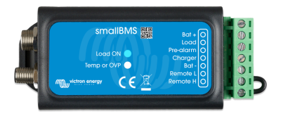
smallBMS with pre-alarm
Victron smallBMS
The Victron Energy smallBMS (previously miniBMS) may be used in place of a VE.Bus BMS in any application with Victron Smart LFP Component batteries that does not have a VE.Bus product on the system. It is not suitable for use with VE.Bus MultiPlus and Quattro inverter/chargers, as it has no VE.Bus interface. The smallBMS can only be used with Victron Smart Component LiFePo4 batteries with M8 circular connectors.
A simple and low cost alternative to the VE.Bus BMS
A simple and low cost alternative to the VE.Bus BMS:
-The smallBMS can replace the VE.Bus BMS in several applications. It is however not suitable for use
with VE.Bus MultiPlus and Quattro inverter/chargers: it has no VE.Bus interface.
-The smallBMS may only be used with Victron Smart LiFePo4 batteries with M8 circular connectors.
-The smallBMS has three outputs, similar to the VE.Bus BMS:
1. Load Disconnect Output
The Load output is normally high and becomes free floating in case of cell under voltage (default
2,8V/cell, adjustable on the battery between 2,6V and 2,8V per cell). Maximum current: 1A. The Load
output is not short-circuit protected.
The Load output can be used to control:
• A high current relay or contactor.
• The remote on/off input of a Battery Protect, inverter or DC-DC converter or other loads.
(a non-inverting or inverting on/off cable may be required, please consult the detailed
manual on our website)
2. Pre-Alarm Output
The pre-alarm output is normally free floating and becomes high in case of imminent cell under
voltage (default 3,1V/cell, adjustable on the battery between 2,85V and 3,15V per cell). Maximum
current: 1A (not short-circuit protected).
The minimum delay between pre-alarm and load disconnect is 30 seconds.
3. Charge Disconnect Output
The Charger output is normally high and becomes free floating in case of imminent cell over voltage
or over temperature. Maximum current: 10mA.
The Charger output is not suitable to power an inductive load such as a relay coil.
The Charger output can be used to control:
• The remote on/off of a charger
• A Cyrix-Li-Charge relay
• A Cyrix-Li-ct Battery Combiner
System on/off input
The system on/off input controls both outputs. When off, both outputs will be free floating so that
loads and chargers are turned off.
The System on/off consists of two terminals: Remote L and Remote H.
A remote on/off switch or relay contact can be connected between L and H.
Alternatively, terminal H can be switched to battery plus, or terminal L can be switched to battery
minus.
Protects 12V, 24V and 48V systems
Operating voltage range: 8 to 70V DC.
LED indicators
• Load ON (blue): Load output high (cell voltage >2.8V, adjustable on the battery).
• Temp or OVP (red): Charger output free floating (due to cell over temperature (>50°C), cell
under temperature (<5 °C) or cell over voltage).